Monday, 14 January 2019

Houdini - erosion

Houdini terrain master class 1


user interface layout can be selected and reset in :
Menu -> Build

Heightfield 

height field is create around the center with the radius as half of the size axis.
grid spacing : large spacing create less resolution.

heightfield paint

paint mask on the height field, need to enable show handle to show the brush
lmb to paint mask
mmb to erase
mouse mmb scroll to change brush size
masked part will show red

heightfield noise

create noise on the height field
input1 : heightfield
input2 heightfield mask


combine Methods : calculation methods btw heighfield and noise


amplitude : change the maxim height of the noise


element size : size of noise


noise type : Worley (cellular ) Manhattan worley is very useful to create chunky flat area on terrain.

geometry and transform & heightfield

geometry can be projected onto a heightfield:


transform node transform the geometry
heightfiel_project project the geometry onto the heightfield.
input1 : heightfield
input2 : geometry

heightfield distort by noise

use noise field to moves the existing values
a compare btw ditort by noise and heightfield noise

heightfield layercomposite two heightfield layers

input 1: hf1
input2 : hf2
input3: maskheightfield File

heightfield file

heightfield file import image to heightfield

heightfiel distort by layer

the distortion can be control by another layer of heightfield 
the distortion keep the shape of the basic terrain layer as well as bring in some feature by the add on layer.
input1 : hf to be distort (terrain)
input2 : addon hf (noise)

compare of before distortion and after
heightfield mask clearer
clear the red mask visually for better

heightfield erosion

visulization: create color scheme for terrain

Place to reset simulation and freeze a frame (where you decided is the final result and don't want to touch it anymore)
to start an erosion : left bottom corner

Global Erosion Rate : higher rate has higher erosion effect

MainTab
  • Hydro : erosion cause by water
Bank Angle : smaller value create wider and flatter river bank, high value cut deep into terrain, a rule of thumb is use high value when creating the basic mass form.
spread iteration : higher number cause the river run longer
  • Thermal erosion : rock becomes sand
cut angle : control where erosion start, low value allow more erosion, higher value create cap on the mountain

advanced Tab
  • Hydro Erosion

removal rate : remove the debris by wind. set to minus can add more debris. It is useful to create muddy effect.

max debris Depth : allow thicker debris build over time.
Grid Bias : Control the direction of erosion

Erodability
initial factor : this increase the strength of erosion 
slope factor : low value enable flat area has erosion, higher value constrain the erosion in sharp slope area.

Riverbed
erosion rate factor : higher value cause deeper cur deep in the river. less value cause scattered isolate lake effect.
deposition rate : higher value cause earth hard to erode.
sediment capacity : how long can sediment go with the water. cause water go further in narrow area, also create mud in flat and wide area.
RiverBank
erosion rate factor : high number cause more erosion on river bank. wider river bank
Max Bank to Bed Water ratio : how much is consider as bank

thermal erosion
has the similar set as hydro erosion

Preciptation
this is where the rain wash down the debris. hydro erosion will need this to take shape.
amount : higher number more rain
density : higher number detail branches on the water path

raindrop setting
expand radius : channel and water area becomes larger in larger value

Debris flow
spread iterations : higher value make debris spread wider
quantization : higher value cause debris to be more chunky
water absorption : the higher value create a muddy and narrow water bank. lower value create wider and flater area.
max height : how high the debris can climb up to the mountain when it is washed down.
repose angle : the angle debris can stand until it falls down


layer
layer is options for multi-layer erosion, either delete or keep previous erosion effect.
remove layer and delete layer :
remove layer still keep the water / debris but they do not calculated in erosion, this is good for adding details on the second layer of erosion
delete layer : useful for when want to keep the form of previous erosion but create data set separately.
add layer to final height : bake the layer to the heightfield

heightfield remap
remap the height of a terrain, normally it will become more realistic.

heightfield blur can be use to blue the heightfield after erosion to create realistic result.


normal noise and chbyshew workey noise to noise but also hard line on top of the mountain, the size of the noise is the key to achieve good result.


heightfield resample
increase the resolution of heightfield
useful when finish the first layer of erosion and before go to the second layer.

heightfield


heightfield_slump


heightfield_flowfield
add the existing flow into the dataset.

Sunday, 13 January 2019

shadow

shadow map theory

shadow map is used to calculate the shadow in real time. 
There are two passes used in this technique

pass 1 , in vertex shader, a z depth is rendered through light view. Pixel shader returns 0. Normally this use render to texture technique, Unity will do it for us here.
pass 2 ,  find out if a pixel is in shader by comparing the distance between the pixel and light and the z depth rendered in 1st pass. Normally shadowmap created from 1st pass will be a sampled here.

shadow acne


one problem of shadow map is shadow acne. 
to calculate if a point is in shadow, it compare its distance to light and the light view depth map.
As the resolution of the light map is limited the camera render pixel can not fully align with lightmap pixel.  When the position request from camera is slightly in front of the light view depth (in fact they should be the same), it will create shadow in the middle of the lit area.


To fix it set the shadow bias

shadow render in Unity

  • shadow casting pass need to be add
LightMode need to be ShadowCaster

Include file "Shadow.cginc" and add the shadow case code in it.
vertex shader is all it needs for shadow caster pass, pixel shader will return 0

a basic process needed is transfer the vertex into clip space.
UnityClipSpaceShadowCasterPos(pos,nor); is used to support normal map
UnityApplyLinearShadowBias(pos); is used for fixing shadow acne
  • Shadow receive pass
multi compile the shadow mode in the light pass that cast shadow:
allocate the memory for shadow map in vertex shadow
SHADOW_COORDS(coordinate number)
try to get the UV coordinate for the shadow map in vertex shader
REANSFER_SHADOW(OUT)

the shadow will be add into the light automatically when using 
UNITY_LIGHT_ATTENUATION

Thursday, 3 January 2019

Houdini - VEX notes


  • Houdini process vertex the similar way as shader

vector ppos = @P;
@P means current point.
@ means either global variable or attribute.


  • use index to get the input of a node , from left to right 0, 1 , 2


It is the opinput in the function
example :


  • write to the attribute

f@distance = distance; // the attribute is a float
v@flow = displacement; // the attribute is a vector


  • add attribute
V@flow = set(0,0,1);
this will add a vector attribute to the current vertex.

Tuesday, 1 January 2019

Unity Shader reference Notes - Multi Light

multi light is done in different passes.

base pass


  • First directional light is in the base pass
  • base pass is drawn no matter if there is a directional light.
  • declare in Tags before CGPROGRAM after pass
  • vertex light need to be in base pass , declare with VERTEXLIGHT_ON


add pass

  • Enable the blending between base and add pass by Blend One One
  • support directional / point / spot light  : multi_compile_fwdadd


include file

include file aim to reuse code include all the vertex / fragment function code and some variables declaration and includes files.
Include is just simple replace all the code in the included file to the including file.
  • a typical including declare is like this. It prevent include the same files twice.

          
  • include file ends with "cginc"
  • base pass and add pass can use the same include file

support different lights

  • according to different light type calculate the light.dir differently
  • UNITY_LIGHT_ATTENUATION(atten , vertextOut , vertextOut. worldPos ) provide the attenuation for point and spot light, it will always be 1 for directional light.


vertex light

  • four vertex lights can be used. When pixel lights reach the set limited, Unity switch to vertex light.
  • to set the pixel light limitation : edit -> project setting -> quality -> pixel light count
  • declare in base pass   #pragma multi_compile _ VERTEXLIGHT_ON
  • In vertex out structure declare vertexLightcolor to pass the vertex light to fragment function
  • light.
          
  • calculate the vertex light using the function ShadePointLight()
          Unity records the vertex lights position, color and attenuation in the following variable


  • vertex light is put into indirect light

          
One thing on vertex light is very important
To force vertex light , put the vertex light to not important render mode in light setting

environment Light

  • environmental light is captured by spherical harmonic function in Unity.
  • the function should only be used in the base pass
  • the function should contribute to the indirect diffuse light.          

Unity Shader reference Notes - before everything else ....

https://catlikecoding.com/unity/tutorials/rendering/

There's a very good tutorial I am following, and I suggest everyone who want to learn Unity Shader follows too.

The author goes into very detail into the Unity's rendering structure and what is happening behind a unity function.  Thus it is very good for deep learning.

For intermediate learner this tutorial does not go directly to the point. It is not the quick reference for getting anything done.

The problem of writing shader in Unity or in any shader environment is that, even though you know the theory of how to wring any shader,  the difference between different environment will prevent you doing it quickly. They provide different variable function and do same thing in different ways.

To have a quick reference is supper important for efficiency. And this is the purpose of this series of blog.

Friday, 14 December 2018

PBR theory and implementation 2

The model used for f(s)is Cook-Torrance

Cook-Torrance approximates the amount of reflected light considering two factor : microfacet and fresnel effect. The equation is :


In this equation Wo is the viewing direction, Wi is the incoming light direction D F G are the three factors affect how much light will be reflected.

D : normal distribution function

F : Fresnel equation

G : Geometry function


microfacet theory


D and G is related to the microfacet theory. The amount of light is reflected relates to smoothness of a surface.

More micro surfaces with reflect vector aligns to the viewing direction more light is reflected to that direction.

More rough the surface , more shadow the surface is casting on itself.


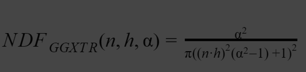
D : Towbridge-Reitx approuch


approximate how much microfacets with reflect vectors align to view direction with a given roughness.

𝛂 : roughness * roughness

h : normalize (L+V)

n : normal of the surface


h= L+V / length (L,H) = normalize (L+V)

This comes from Blinn_Phong lighting model, instead of evaluating the alignment between view vector and reflect vector, evaluating the Normal vector and Halfway vector of incoming light and view direction.

The correct implimentation of D will be look like :


G : Schlick - GGX approximation


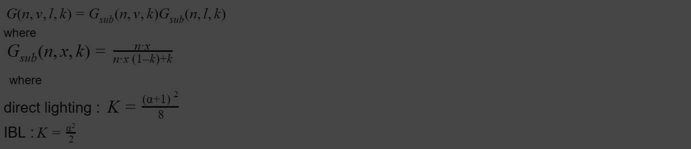
It approximate how much self shadowing will generate given a certain roughness lighting direction and view angle.


The reason it is calculated twice on light vector and view vector is that both of these are affecting how much shadow can be seen.

k is a remapping for . Different lighting situation will need different remapping.

The correct implimentation of G will be look like :


Fresnel schlick approximation

Fresnel equation describe how much light is reflected given a viewing angle and the base reflectivity.

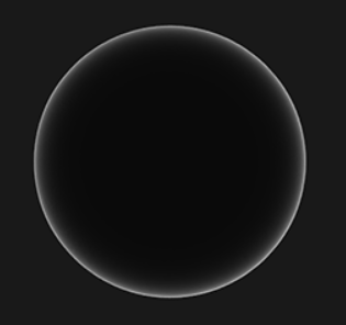
Fresnel effect : the amount of reflected light changes with viewing angle. At grazing angle all material can fully reflect light.


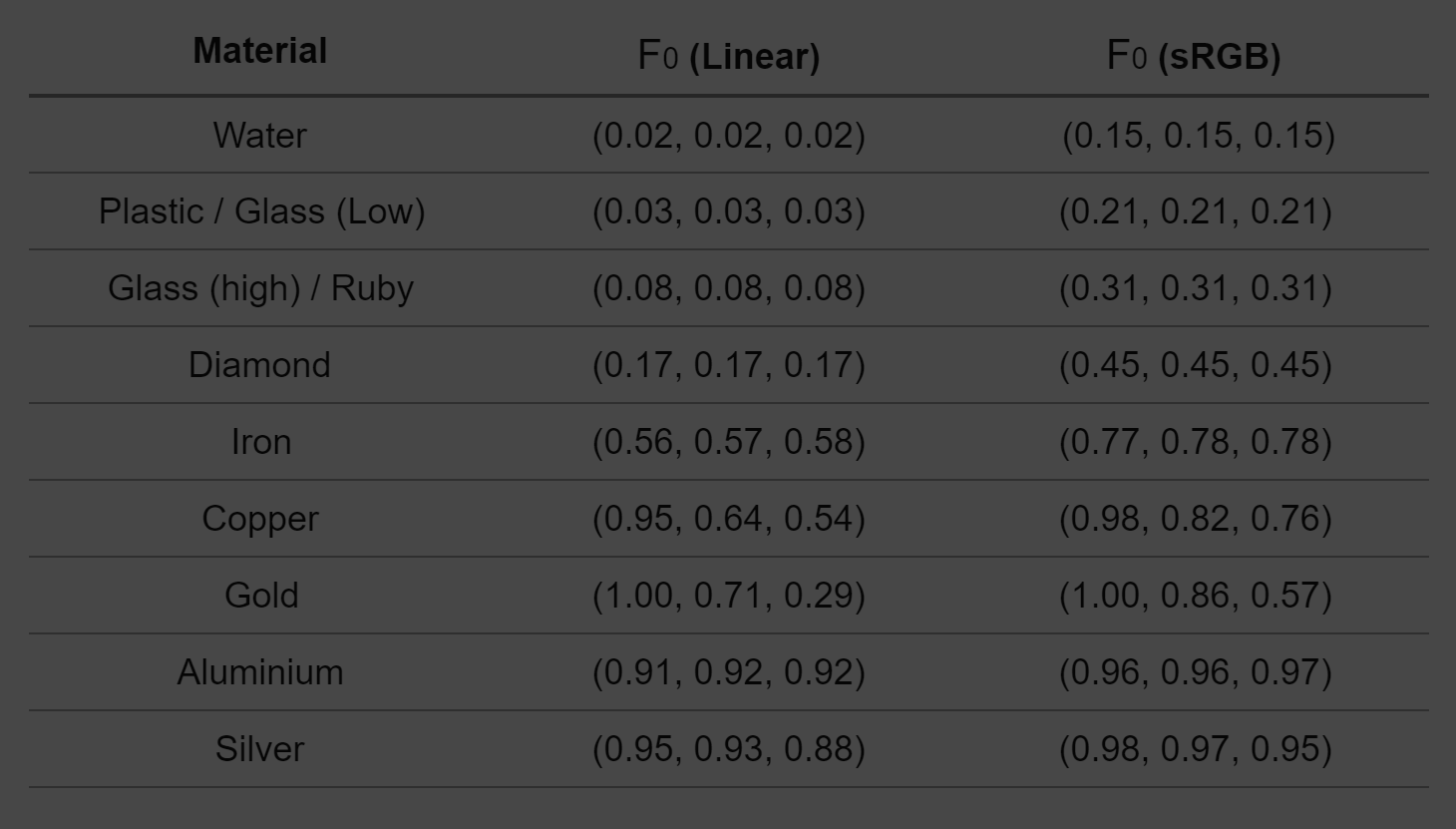
Base reflectivity F0 : describe how much light is reflected when viewing angle is aligned to a surface normal. Different material will have different base reflectivity.

Metal has a higher F0(0.5~1.0) , usually tinted(it is a sRGB). Dielectricity has lower F0(<0.17)

a useful reference chart can be found here


we lerp the value between reflectivity of metall F0-SRGB and a reflectivity of dielecctric 0.04 with the value of the metalic.
The second equation

Distribute outgoing light energy according to the material and form. For example, metal reflect environment much more than dielectric material. It also has a fancy name : BRDF.


correct implimented Fresnel schlick approximation will look like this


When implimenting the equation, we found the precious equation is not matermaticcaly correct , if we use cook-torrance BRDF , because cook-torrance already include the Ks part (how much light is reflected) by having fresnel equation.
Thus , the equation change from :
Lo =(Kd*f(d) +Ks*f(s) ) * Li
to :
Lo =(Kd*f(d) +cook-torrance ) * Li

Wednesday, 12 September 2018

PBR theory and implementation 1


This article is mainly for my own studying, thus only very key fact will be explain here.

My implementation is in HLSL DirectX 11 in 3ds max environment.

You can see the result in the following image


reference

I read through a lot of article many times to fully understand the theory as well as the math behind this. The ones I reference a lot is :


Very good open gl PBR tutorial

https://learnopengl.com/PBR/Theory

many images in my notes is from here as well

Unity shader source code

Since I want to concentrate on shading I didn’t implement precalculate radiance map and lut this time, I reference Unity’s implementation on real time IBL.

what is PBR ?

Normally you see result images like this when talking about PBR


PBR stands for Physically Based Rendering : The way we calculate the lighting and shading (how different material react to the lighting) follow the physical rules. This will divided the topic into two parts : PBL (physically based lighting ) and PBS (physically based shading)

The target of rendering is : Calculate the light on a surface point by knowing the surface point(p), incoming light direction(i) and strength(Li), view direction(o).

Lo(p,o ) = f(p,i,Li,o)


Traditional lighting model and PBR is doing the same thing but PBR calculate more factors to simulate the real life result.

Energy conservation

One key rule : The radiance(light) comes out from one object can never exceed the light hit on the object.


outgoing light = incoming light

specular and Diffuse distribution

outgoing light from a lit surface falls into two parts : specularand diffuse.


yellow : specular, Light directly get reflected.

red : diffuse , Light get absorbed then comes out from the surface again.


different speculator/diffuse distributions defines the look of different material.


Metal only has speculator, because all the light energy that goes into the surface get absorbed.


To render physically correct means to find the correct distribution between diffuse and specular. In math term it will be something like this:


outgoing light =(diffuse scale+ specular scale) incoming light


because of Energy conservation.


diffuse scale+ speculator scale =1

Material and angle distribution

The next step will be calculate the outcoming light value (r,g,b) given a vertain viewing angle (w0) , incoming light direction (wi) , surface condition (roughness) and material (gold , mud ..)

In other words, how the roughness, metalness, viewing angle , normal ... affect the final result of the outcoming light. How is gold different from mud.

I call it disreibution for now,

view angle light =(diffuse fraction* diffuse distribution + specular fraction* specular distribution) * incoming light

let’s put :

Kd : diffuse fraction

Ks : specular fraction

Li: incoming lighti

Lo : out going light at o

f(d):diffuse distribution

f(s):specular distribution


the equation will be like:


Lo =(Kd*f(d) +Ks*f(s) ) * Li


The reason we seperate f(d) and f(s)is diffuse distribution is different from specular distribution.

In diffuse distribution we use Lambert law (viewing angle does not affect the light value )
In specular , cook-torrance (an advanced relflect / mirror effect)

Render equation

Lo =(Kd*f(d) +Ks*f(s) ) * Li is the Render equation

and Kd*f(d) +Ks*f(s) is the BRDF

BRDF

BRDF Bidirectional reflective distribution function approximates how much each individual light ray i contributes to the final reflected light of an opaque surface given its material properties.


the one used in real time rendering is Cook - Torrance BRDF.


The model used for f(d)is Lambert diffuse : The apparent brightness of a Lambertian surface to an observer is the same regardless of the observer’s angle of view.


f(d) = C/Pi


C is the albedo.