Showing posts with label shader. Show all posts

Saturday, 19 January 2019

PBR theory and implementation 3

  • Calculating the Lighting 

To calculate the irradiance that hit on the point we need to calculate the sum of all the lights from all directions that hit on the point.


To do this we need to calculate the integral of the incoming light over the dome.

given light strength on point p from direction ωi : L(p,ωi)


With all the knowledge of BRDF and irradiance, the Cook-Torrance reflectance equation will look like this:



Direct Light

For direct light, it is simple, we don't need to consider the integral over the whole dome.

We just need to scale the light by cos theta (The angle between the light vector and normal vector).

IBL

The environmental light is a bit tricky. Environmental light is the whole environment is light source and lit up the target surface. It is crucial to for realistic rendering. But calculate all light from all direction is nearly impossible in the realtime rendering (I say nearly here because the latest hardware and framework like RTX starts to support real-time raytrace rendering ) we use the environmental texture as the light source to mimic the environment light. This technique is call image base lighting or IBL.

Calculating intergral is very heavy in real time, to solve this problem,
we divide the render equation into two part :


left side is the diffuse part, right side is the specular part.

diffuse IBL

The result of the diffuse IBL only relate to ωi, sample direction on the environment map. This enable us precalculate the integral of the intergral of the the texture and svae it to a new texture, this is called irradiance map.

 In run time, we do :


an image from Wave engine to show the different between a environment map and irradiance map :


my inplementation detail :
I don't have the preculculated irradiance map , I could have write a CPP programme to caiculate it on CPU...

I simply use the mipmap to get the blur effect

Specular IBL

divide the right part into two parts:


  • Pre-filtered environmental map


The left part is called Pre-filtered environmental map, it calculate the sum of lights contribute to the final reflection. In diffuse light, lights from all direction are calculated. For specular only small part of the light are affecting the result. Perfect mirror has perfecti reflection, light can only be seen on reflect vector ; rough metal has a scattered reflection because more light can be observed. 


The rougher the surface is, lights from bigger range is affect the reflection at viewing direction.
The result will be


The higher the mipmap is , more sample is used to make the integral, this also means rougher the surface is.


  • BRDF intergration map


My implementation detail :

I use importance sampling to approximate the radiance intergral

I reference Real Shading in Unreal Engine 4 to implement the specular IBL

Friday, 14 December 2018

PBR theory and implementation 2

The model used for f(s)is Cook-Torrance

Cook-Torrance approximates the amount of reflected light considering two factor : microfacet and fresnel effect. The equation is :


In this equation Wo is the viewing direction, Wi is the incoming light direction D F G are the three factors affect how much light will be reflected.

D : normal distribution function

F : Fresnel equation

G : Geometry function


microfacet theory


D and G is related to the microfacet theory. The amount of light is reflected relates to smoothness of a surface.

More micro surfaces with reflect vector aligns to the viewing direction more light is reflected to that direction.

More rough the surface , more shadow the surface is casting on itself.


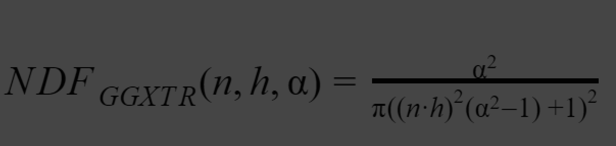
D : Towbridge-Reitx approuch


approximate how much microfacets with reflect vectors align to view direction with a given roughness.

𝛂 : roughness * roughness

h : normalize (L+V)

n : normal of the surface


h= L+V / length (L,H) = normalize (L+V)

This comes from Blinn_Phong lighting model, instead of evaluating the alignment between view vector and reflect vector, evaluating the Normal vector and Halfway vector of incoming light and view direction.

The correct implimentation of D will be look like :


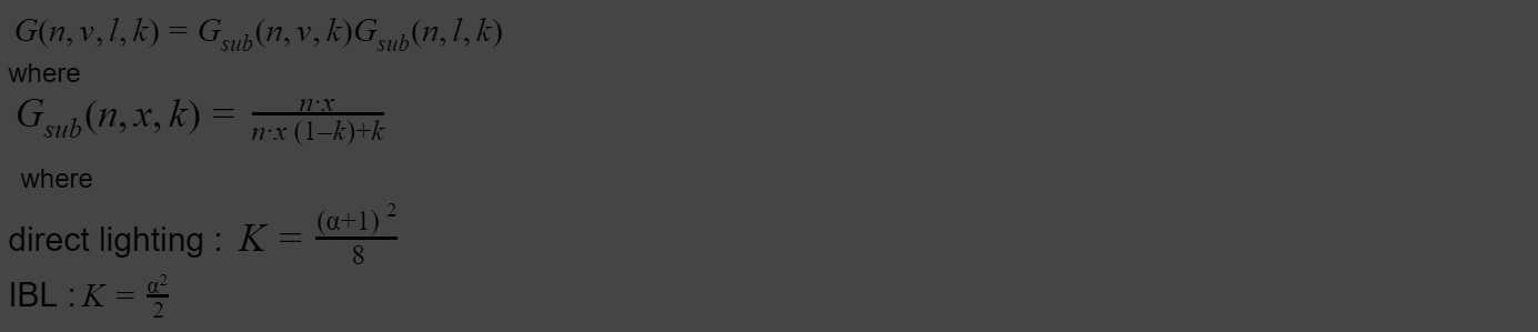
G : Schlick - GGX approximation


It approximate how much self shadowing will generate given a certain roughness lighting direction and view angle.


The reason it is calculated twice on light vector and view vector is that both of these are affecting how much shadow can be seen.

k is a remapping for . Different lighting situation will need different remapping.

The correct implimentation of G will be look like :


Fresnel schlick approximation

Fresnel equation describe how much light is reflected given a viewing angle and the base reflectivity.

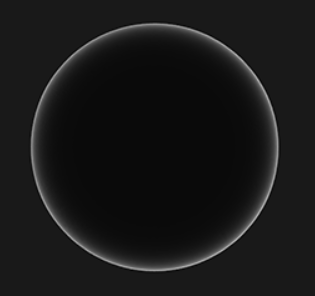
Fresnel effect : the amount of reflected light changes with viewing angle. At grazing angle all material can fully reflect light.


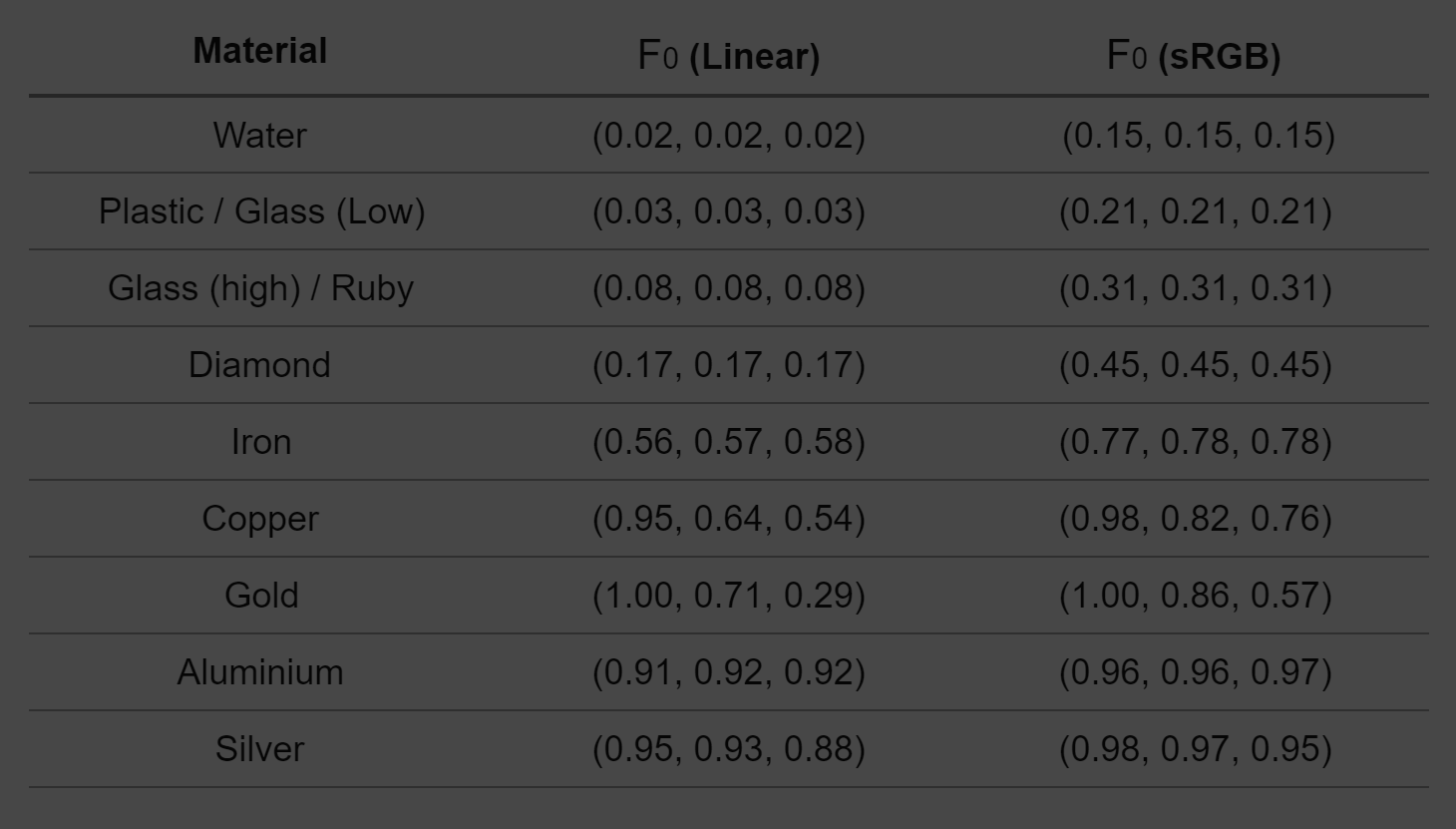
Base reflectivity F0 : describe how much light is reflected when viewing angle is aligned to a surface normal. Different material will have different base reflectivity.

Metal has a higher F0(0.5~1.0) , usually tinted(it is a sRGB). Dielectricity has lower F0(<0.17)

a useful reference chart can be found here


we lerp the value between reflectivity of metall F0-SRGB and a reflectivity of dielecctric 0.04 with the value of the metalic.
The second equation

Distribute outgoing light energy according to the material and form. For example, metal reflect environment much more than dielectric material. It also has a fancy name : BRDF.


correct implimented Fresnel schlick approximation will look like this


When implimenting the equation, we found the precious equation is not matermaticcaly correct , if we use cook-torrance BRDF , because cook-torrance already include the Ks part (how much light is reflected) by having fresnel equation.
Thus , the equation change from :
Lo =(Kd*f(d) +Ks*f(s) ) * Li
to :
Lo =(Kd*f(d) +cook-torrance ) * Li

Wednesday, 12 September 2018

PBR theory and implementation 1


This article is mainly for my own studying, thus only very key fact will be explain here.

My implementation is in HLSL DirectX 11 in 3ds max environment.

You can see the result in the following image


reference

I read through a lot of article many times to fully understand the theory as well as the math behind this. The ones I reference a lot is :


Very good open gl PBR tutorial

https://learnopengl.com/PBR/Theory

many images in my notes is from here as well

Unity shader source code

Since I want to concentrate on shading I didn’t implement precalculate radiance map and lut this time, I reference Unity’s implementation on real time IBL.

what is PBR ?

Normally you see result images like this when talking about PBR


PBR stands for Physically Based Rendering : The way we calculate the lighting and shading (how different material react to the lighting) follow the physical rules. This will divided the topic into two parts : PBL (physically based lighting ) and PBS (physically based shading)

The target of rendering is : Calculate the light on a surface point by knowing the surface point(p), incoming light direction(i) and strength(Li), view direction(o).

Lo(p,o ) = f(p,i,Li,o)


Traditional lighting model and PBR is doing the same thing but PBR calculate more factors to simulate the real life result.

Energy conservation

One key rule : The radiance(light) comes out from one object can never exceed the light hit on the object.


outgoing light = incoming light

specular and Diffuse distribution

outgoing light from a lit surface falls into two parts : specularand diffuse.


yellow : specular, Light directly get reflected.

red : diffuse , Light get absorbed then comes out from the surface again.


different speculator/diffuse distributions defines the look of different material.


Metal only has speculator, because all the light energy that goes into the surface get absorbed.


To render physically correct means to find the correct distribution between diffuse and specular. In math term it will be something like this:


outgoing light =(diffuse scale+ specular scale) incoming light


because of Energy conservation.


diffuse scale+ speculator scale =1

Material and angle distribution

The next step will be calculate the outcoming light value (r,g,b) given a vertain viewing angle (w0) , incoming light direction (wi) , surface condition (roughness) and material (gold , mud ..)

In other words, how the roughness, metalness, viewing angle , normal ... affect the final result of the outcoming light. How is gold different from mud.

I call it disreibution for now,

view angle light =(diffuse fraction* diffuse distribution + specular fraction* specular distribution) * incoming light

let’s put :

Kd : diffuse fraction

Ks : specular fraction

Li: incoming lighti

Lo : out going light at o

f(d):diffuse distribution

f(s):specular distribution


the equation will be like:


Lo =(Kd*f(d) +Ks*f(s) ) * Li


The reason we seperate f(d) and f(s)is diffuse distribution is different from specular distribution.

In diffuse distribution we use Lambert law (viewing angle does not affect the light value )
In specular , cook-torrance (an advanced relflect / mirror effect)

Render equation

Lo =(Kd*f(d) +Ks*f(s) ) * Li is the Render equation

and Kd*f(d) +Ks*f(s) is the BRDF

BRDF

BRDF Bidirectional reflective distribution function approximates how much each individual light ray i contributes to the final reflected light of an opaque surface given its material properties.


the one used in real time rendering is Cook - Torrance BRDF.


The model used for f(d)is Lambert diffuse : The apparent brightness of a Lambertian surface to an observer is the same regardless of the observer’s angle of view.


f(d) = C/Pi


C is the albedo.